COGNITIVE NEUROIMAGING LAB
The INSERM-CEA Cognitive Neuroimaging Unit, directed by Stanislas Dehaene, Professor at Collège de France, comprises five teams:
Languages of the Brain
Directed by Christophe Pallier
Why are we the only species with a sophisticated communication system using a combinatorial language, as well as a capacity to develop languages in many other domains, such as music or mathematics? Our aim is to elucidate the brain systems that allow humans to represent and manipulate abstract symbols, algebraic rules and recursively embedded representations, not only for language but also in other domains such as the planning of complex actions. Do these domains rely on similar brain circuits of recent evolution? Our current efforts concentrate on the questions of how the human brain learns and encodes linguistic and non-linguistic structures
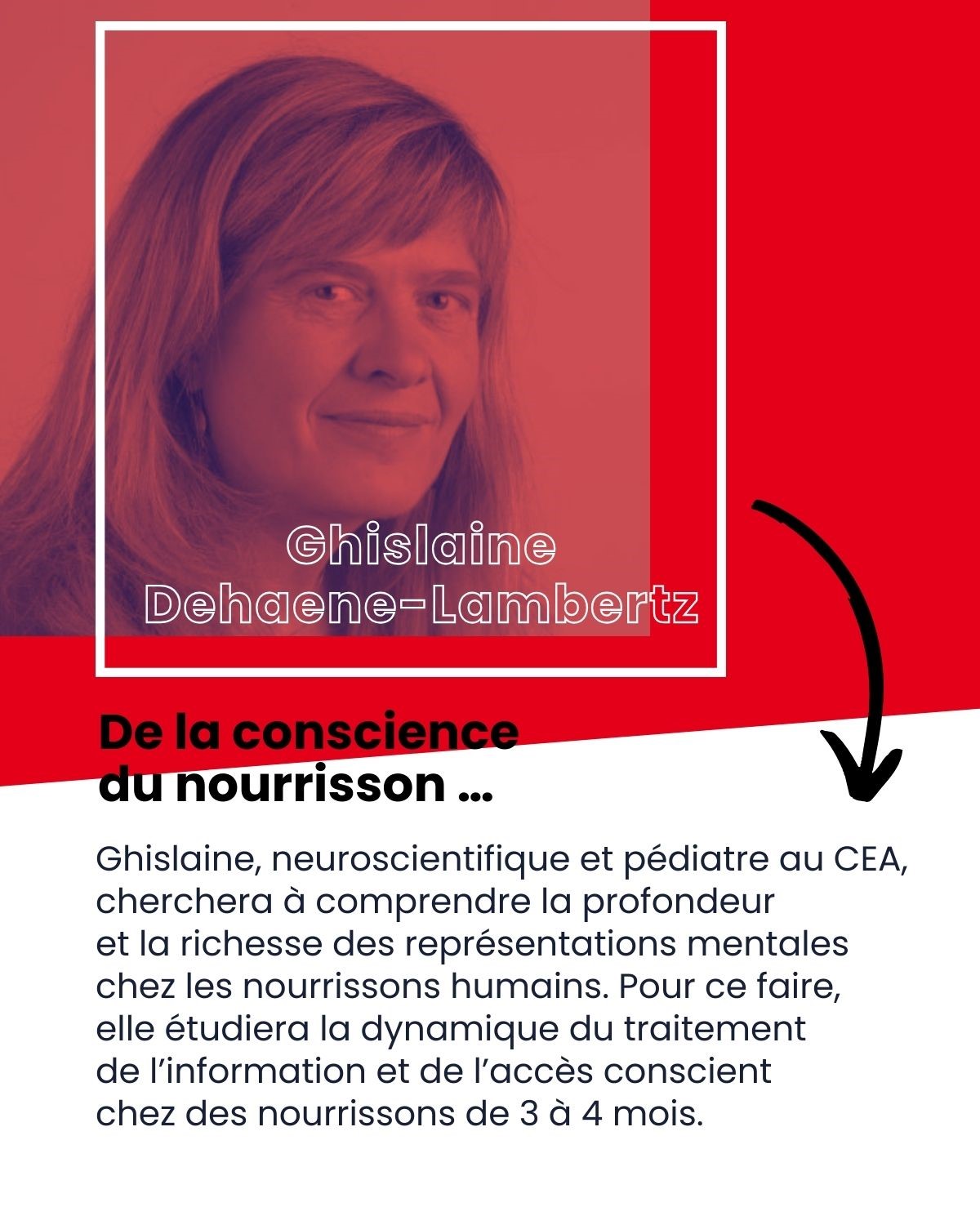
Neuroimaging of Development
Directed by Ghislaine Dehaene-Lambertz, DRCE CNRS
We examine human cognitive development in infants and children, both at the structural and functional levels, and to develop new imaging techniques adapted to human infants.
You can follow our work here (in French Mon cerveau à l’école)
Neuromodulation
Directed by Béchir Jarraya, Professor at University of Versailles Paris Saclay
We analyze the primate brain functions, and evaluate their modulation by pharmacological agents or electrical neurostimulations.
Cognition and Brain dynamics
Directed by Virginie van Wassenhove, DR CEA
We evaluate the processing of multisensory information, its temporal organization and particularly the representation of temporal information in the human brain, using magnetoencephalography (MEG) as a principal method.
The Computational Brain
Directed by Florent Meyniel, CEA
Our team studies various functions of the human brain from the viewpoint of computations. Our goal is to propose quantitative models of brain functions, algorithms for the processing of information and identity the neural codes that subtend them.
If you are interested in participating as volunteer in our research / Pour participer à des expériences de psychologie ou d’imagerie cérébrale, rendez vous sur ce site:
https://joliot.cea.fr/drf/joliot/Pages/Entites_de_recherche/neurospin/Participer-a-la-recherche.aspx